Introduction
As part of an eight-person team, I led the control system design and analysis and played a key role in manufacturing a UAV for a two-semester capstone project. I was responsible for developing the aircraft’s flight control system, integrating and tuning the autopilot, and designing and manufacturing 3D printed parts, ensuring a strong airframe and stable flight performance. Our team placed second overall in the competition, with our primary trade-offs being a slightly reduced flight time due to prioritizing weight savings over increased battery capacity, and harder to access internals to simplify manufacturing.
Mission Requirements
We were tasked with designing a small unmanned aerial system (sUAS) that could:
- Launch from a 10-foot ramp
- Fly for at least 45 minutes
- Collect weather data via a customer-supplied payload
- Have a maximum takeoff weight of 10 lbs
- Achieve an optimal cruise velocity of 30 knots
- Break down into components under 50 inches for transport
- Solar recharge capability for extended missions
Additionally, our team set secondary goals:
- Toolless assembly for quick deployment
- A factor of safety of at least 2 for structural integrity
Design
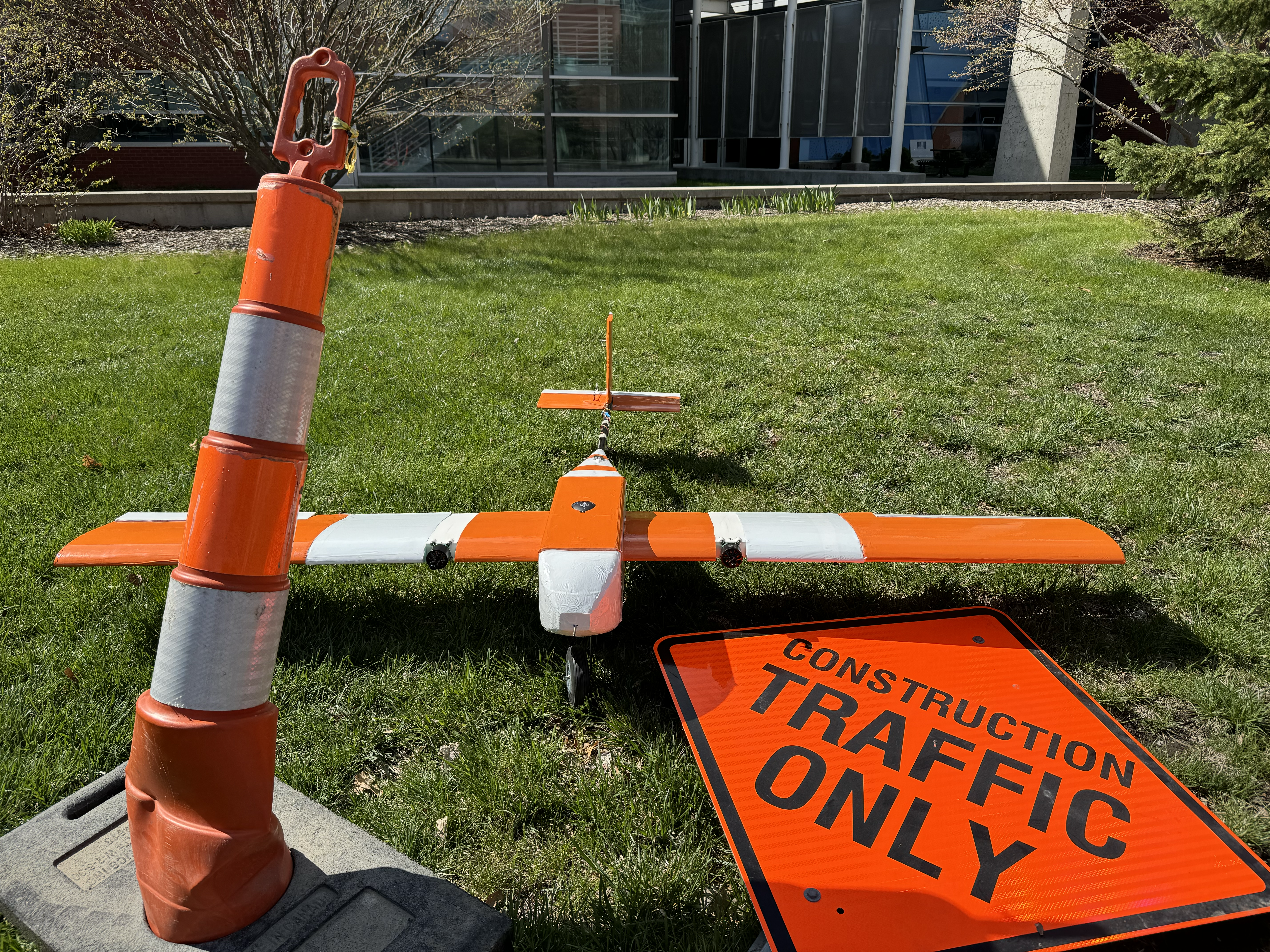
The final design
Our first semester was spent designing the aircraft. We selected a conventional fixed-wing configuration. Using XFLR5, we analyzed over 20 airfoils and selected the one with the highest L/D ratio at 30 knots to maximize endurance. We extruded the airfoil into a high aspect ratio wing to maximize efficiency, sizing it to maximize L/D, using Carbon Fiber (CF) spars for weight reduction and stiffness, and foam for lightweight aerodynamic surfaces. The fuselage was cut out of 1/8” lightweight plywood, providing a balance of structural strength and weight savings while minimizing cost. Aerodynamic nose and tail cones were fitted to the fuselage to reduce drag. Tail sizing was determined based on tail volume coefficients before being verified with CFD. To meet both takeoff and cruise time requirements, we implemented a twin-motor configuration which we simulated using eCalc.
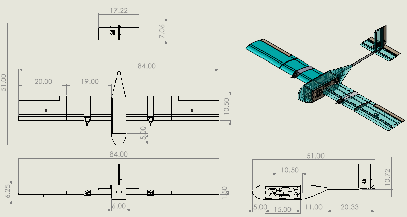
The aircraft was split into four modular sections (as can be seen in the photo above) to meet transport constraints:
- Two outer wings attached via CF ferrules and magnets
- A tail assembly secured with a pin and ferrule mechanism
- The main fuselage housing avionics and payload
These sections were chosen to maximize strength while keeping all parts under the required 50 inches. At the end of this semester, our design was finalized, and we presented a Critical Design Review. No deficiencies were found with our design, and only minor changes were recommended (such as switching the type of heat-set inserts we planned on using). With the approval, we began manufacturing and assembling the aircraft.
Manufacture and Assembly

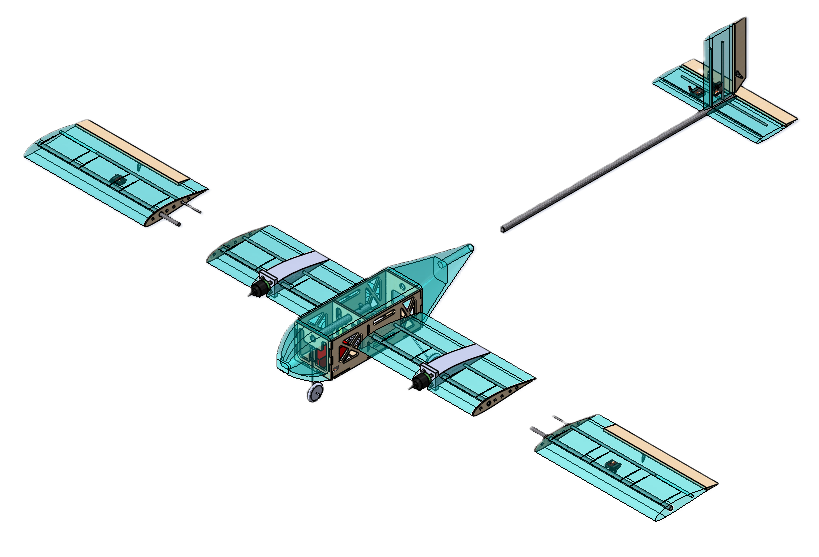
A promotional image of our prototype
To balance weight, cost, and manufacturability, we used a combination of laser-cut plywood, carbon fiber tubing, hot-wire-cut foam, and 3D printing. The fuselage was constructed from laser-cut plywood, simplifying manufacturing compared to composite alternatives. The wings and tail used foam aerodynamic surfaces with CF spars to minimize weight while ensuring structural rigidity. The motor nacelles were 3D-printed from lightweight PLA, allowing complex surfaces to be easily manufactured. 3D printed jigs were also used to increase precision when cutting and drilling CF, reducing errors and build time. The control systems were integrated into the aircraft and tested before the structure was monocoated to enhance aerodynamics. Before flight, weights were used to test the aircraft to 3.5G to ensure it would stand up to in-flight loading. The control and data collection systems were tested one final time before the aircraft was brought to the airfield for flight testing.
Testing
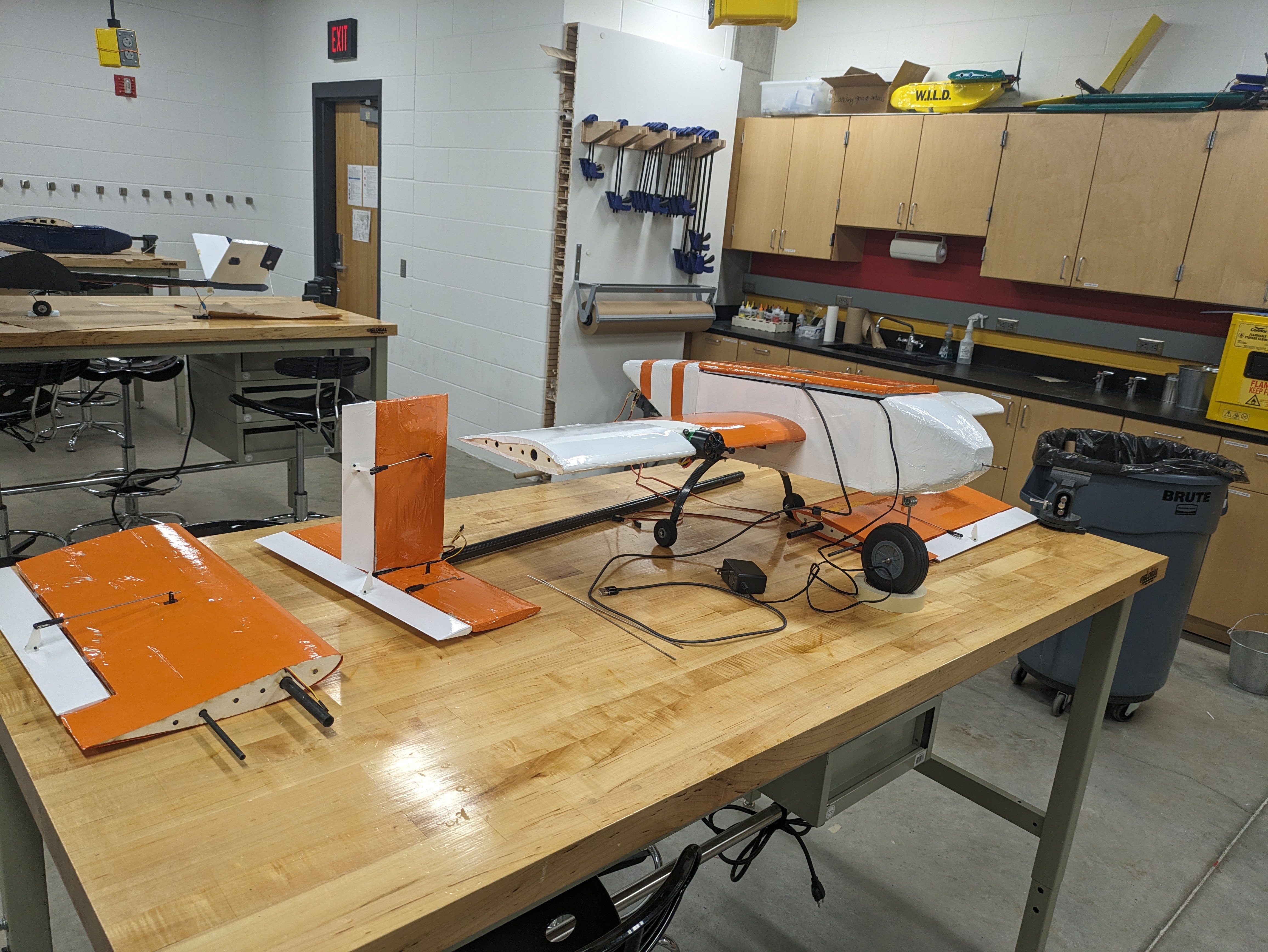
The prototype undergoing testing
The prototype aircraft was tested at the local model airfield and passed all required flight tests. The aircraft remained stable throughout testing, and the pilots noted that it was one of the easiest to fly, requiring only minor trimming. The flight time was shorter than calculated; however, our team anticipated this and oversized the battery accordingly, ensuring we met the flight time requirements.
Final Results
Time and weather constraints did not allow for any group to complete full testing, however our UAV successfully met all mission requirements except for a full-speed test (which was omitted for time). However, prior flight data recorded an airspeed of 38 knots, and computational models suggested a top speed exceeding the required 40 knots. Our aircraft ranked second among all competitors, excelling in flight stability and endurance.
Key Takeaways
Our design methodologies worked well and produced a high performing aircraft. Our biggest lesson was that early communication with stakeholders is critical; clarifying customer priorities on endurance vs. weight would have influenced our design decisions. Overall, my contributions in control system design, manufacturing optimization, and structural validation played a major role in our UAV’s strong competition performance.